Physics Notes - Herong's Tutorial Notes - v4.01, by Herong Yang
What Is Magnetic Torque
This section provides a quick introduction of of magnetic dipole and its moment.
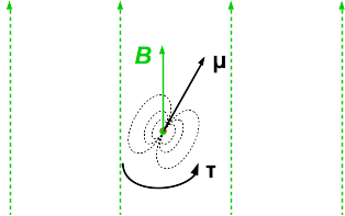
What Is Magnetic Torque? A Magnetic Torque, τ (tau), is a vector value that represents the rotational force exerted by an external magnetic field on a magnetic dipole. It is defined as the cross product of the magnetic field vector at the location of dipole and the dipole moment:
        τ = μ × B
where:
        τ is the torque exerted on the dipole
        μ is the dipole moment
        B is the magnetic field vector
        × is the cross product operation for vectors
The diagram below shows you the torque exerted on a dipole by an external uniform magnetic field. The direction of the torque is pointing out of the diagram.
If the dipole represents the magnetic field created by a wire loop, we can calculate the magnetic torque directly from magnetic forces exerted on moving charges in the wire loop.
Magnetic Torque on Rectangular Wire Loop - Let's consider a rectangular wire loop in a uniform magnetic field first. It's the easiest case to analyze.

If we align 2 opposite vertical sides of the wire along the direction of the magnet field as show in the diagram below, there will no magnetic force on both vertical sides.
The magnetic force, F1, on the upper side can be calculated using the formula presented in the "Magnetic Force on Wire Rod" section:
        F1 = b(I × B)
        F1 = bI |B|
where:
        The magnitude of the cross product is taken
This magnetic force produces a torque to rotate the wire around its center line:
        |τ1| = rF1
            = rbI |B|
            = 0.5abI |B|
            = 0.5AI |B|
where:
        r = 0.5a is the radius of the rotation
        A is the area of the rectangle wire loop
Similarly, the magnetic force, F2, on the lower side also produces a torque with the same magnitude:
|τ2| = 0.5AI |B|
So the combined torque on the wire is:
        |τ| = |τ1| + |τ2|
           = 0.5AI |B| + 0.5AI |B|
           = AI |B|
where:
        A is the area of the rectangle wire loop
        I is the current in the wire
        |B| is the magnetic field magnitude
Note that the above formula actually gives the maximum torque magnitude, when the plane of the wire loop is aligned to the magnetic field direction.
Now if we approximate the rectangle wire loop as a magnetic dipole, the magnetic torque is defined as:
τ = μ × B
Based on the definition of cross production, the maximum magnitude of the magnetic torque is:
|τ| = |μ| |B|
Compare this definition with the calculation result, we can obtain the approximate dipole moment of a rectangle wire loop:
|μ| = AI
Magnetic Torque on Circular Wire Loop - Calculating the magnetic torque directly from magnetic forces exerted on moving charges in a circular wire loop requires integration of infinitesimal wire segments.
Let's start with a single segment on the loop. The differential magnetic force can be calculated as:
        dF = I |B| sin(θ) dl
             = I |B| r sin(θ) dθ
where:
        I is the current in the wire loop
        |B| is the magnetic field magnitude
        r is the radius of the wire loop
        dl = r dθ is applied
        θ is the angle from the rotation axis to the segment
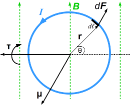
This differential magnetic force produces a differential torque to rotate the wire around its axis:
        d|τ| = r sin(θ) dF
            = r sin(θ) I |B| r sin(θ) dθ
            = I |B| r2 sin2(θ) dθ
The total magnetic torque over the upper half of the loop is the integration of the infinitesimal torque:
where:
        sin2(θ) = 0.5(1 - cos(2θ)) is applied
        ∫ (1 - cos(2θ)) = θ - 0.5 sin(θ) is applied
        A = π r2 is the area of the circular loop
Similarly, the total magnetic torque over the lower half of the loop has the same magnitude:
|τ2| = 0.5AI|B|
So the combined torque on the wire is:
        |τ| = |τ1| + |τ2|
          = 0.5AI|B| + 0.5AI|B|
          = AI|B|
where:
        A is the area of the circular wire loop
        I is the current in the wire
        |B| is the magnetic field magnitude
Note that the above formula actually gives the maximum torque magnitude, when the plane of the wire loop is aligned to the magnetic field direction.
Magnetic Torque on Any Flat Wire Loop - From both cases analyzed above, the maximum magnetic torque magnitudes on rectangle wire loop and circular wire loop share the same formula:
|τ| = AI|B|
It can be approved that this formula is valid for calculating the maximum magnetic torque magnitude on any flat wire loop. So formulas below are for any flat wire loop:
        |τ| = AI|B|
        |μ| = AI
        μ = AIn
        τ = μ × B
where:
        μ is the dipole moment
        A is the area of the wire loop
        I is the current in the wire
        B is the magnetic field vector
        τ is the torque exerted on the dipole
        n is the unit normal vector of the wire loop
        × is the cross product operation for vectors
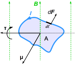
Table of Contents
Introduction of Frame of Reference
Magnetic Force on Moving Charges
Moving Charge Creating Magnetic Field
Biot-Savart Law for Magnetic Fields
Magnetic Fields of Current Carrying Loops
What Is Magnetic Dipole and Moment
Introduction of Special Relativity
Time Dilation in Special Relativity
Length Contraction in Special Relativity
The Relativity of Simultaneity
Minkowski Spacetime and Diagrams
Introduction of Generalized Coordinates