UML Tutorials - Herong's Tutorial Examples - v1.05, by Herong Yang
State Machine Diagram - Transition Notation
This section describes the Transition Notation used in a UML State Machine Diagram. A Transition Notation presents a behavior change of the modeled object from one state to another.
A Transition Notation is the primary graphical notation used in a UML State Machine Diagram to represent a behavior change of the modeled object from one state to another.
A Transition Notation is drawn as a solid line with a line arrow pointing from the previous state to the next state. A Transition Notation may be labeled with the conditions and actions that related to this transition.
For example, the transition from "Door Locked" state to "Door Unlocked" state requires a condition of "Have key" and an action of "Unlock". This transition can be drawn as a Transition Notation in a UML State Machine diagram as shown below:
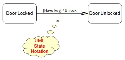
Table of Contents
Introduction of UML (Unified Model Language)
UML Class Diagram and Notations
UML Activity Diagram and Notations
UML Sequence Diagram and Notations
►UML State Machine Diagram and Notations
What Is a State Machine Diagram?
State Machine Diagram - State Notation
State Machine Diagram - Pseudostate Notations
►State Machine Diagram - Transition Notation
State Machine Diagram - Transition Sequence Notations
UML Use Case Diagram and Notations
LibreOffice Drawing Extension - UML Elements