UML Tutorials - Herong's Tutorial Examples - v1.05, by Herong Yang
Sequence Diagram - Execution Specification Notation
This section describes the Execution Specification Notation used in a UML Sequence Diagram. An Execution Specification Notation presents the execution of action unit within a lifeline of an object.
An Execution Specification Notation is a graphical notation used in a UML Sequence Diagram to represent the execution of action unit within a lifeline of an object.
An Execution Specification Notation is drawn as a narrow rectangle shape attached to the lifeline of its object. Sometimes a wider rectangle shape can be used to include the action name. For example, Executions of actions will be triggered in the lifeline of a "Web Server" object to react to incoming messages. These executions can be drawn as a Lifeline in a UML sequence diagram as shown below:
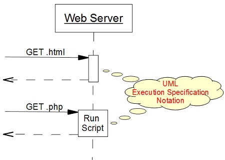
Note that in some UML drawing tools, Execution Specification Notation is called Activation notation
Table of Contents
Introduction of UML (Unified Model Language)
UML Class Diagram and Notations
UML Activity Diagram and Notations
►UML Sequence Diagram and Notations
Sequence Diagram - Lifeline Notation
Sequence Diagram - Message Notation
►Sequence Diagram - Execution Specification Notation
Sequence Diagram - Frame Notation
UML State Machine Diagram and Notations
UML Use Case Diagram and Notations
LibreOffice Drawing Extension - UML Elements