UML Tutorials - Herong's Tutorial Examples - v1.05, by Herong Yang
Component Diagram and Notations in Visio
This section lists UML Component Diagram notations supported in MS Visio 2010.
If you are using the "UML Model Diagram" template in Visio 2010 and select the "UML Component (Metric)" notation group, you will see it support the following notations:
Node
Component
Package
Interface
Dependency
Constraint
Note
2-element Constraint
OR Constraint
The picture below shows you notation shapes related to Component Diagrams that are supported in Vision 2010:
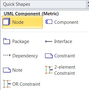
Table of Contents
Introduction of UML (Unified Model Language)
UML Class Diagram and Notations
UML Activity Diagram and Notations
UML Sequence Diagram and Notations
UML State Machine Diagram and Notations
UML Use Case Diagram and Notations
►MS Visio 2010 - UML Drawing Tool
Visio 2010 UML Model Diagram Template
Activity Diagram and Notations in Visio
Collaboration Diagram and Notations in Visio
►Component Diagram and Notations in Visio
Deployment Diagram and Notations in Visio
Sequence Diagram and Notations in Visio
Statechart Diagram and Notations in Visio
Static Diagram and Notations in Visio