UML Tutorials - Herong's Tutorial Examples - v1.05, by Herong Yang
Use Case Diagram - Include Notation
This section describes the Include Notation used in a UML Use Case Diagram. An Include Notation presents an include relation between two use cases where one acts as the parent use case and the other acts as a child use case.
An Include Notation is a graphical notation used in a UML Use Case Diagram to represent an include relation between two use cases where one acts as the parent use case and the other acts as a child use case. The child use case is considered as a subset of the parent use case. The parent use case is usually called the Including Use Case. The child use case is usually called the Included Use Case.
An Include Notation is usually drawn as a dash line with a line arrow connecting both use cases. The arrow of an Include Notation should point to the included use case. An Extend Notation should also be labeled with the "<<include>>" key word.
For example, the "Select Product" use case is a child use case of the "Place Order" use case. In other words, the "Place Order" use case contains the "Select Product" use case as a subset. This include relation can be drawn as an Include Notation in a UML use case diagram as shown below:
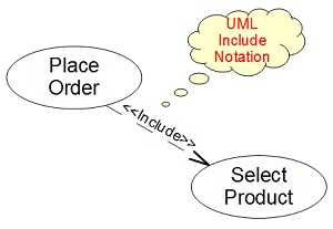
Table of Contents
Introduction of UML (Unified Model Language)
UML Class Diagram and Notations
UML Activity Diagram and Notations
UML Sequence Diagram and Notations
UML State Machine Diagram and Notations
►UML Use Case Diagram and Notations
Use Case Diagram - Use Case Notation
Use Case Diagram - Actor Notation
Use Case Diagram - Association Notation
Use Case Diagram - Extend Notation
►Use Case Diagram - Include Notation